03 April 2017
Eddy Current Testing
Eddy current testing is an inspection method that can be used for a variety of purposes including the detection of cracks and corrosion, material and coating thickness measurement, material identification and, in certain materials, heat treatment condition. The process relies upon a material characteristic known as electro-magnetic induction. When an alternating current is passed through a conductor – a copper coil for example – an alternating magnetic field is developed around the coil, the field expanding and contracting as the alternating current rises and falls. If the coil is then brought close to another electrical conductor the fluctuating magnetic field surrounding the coil permeates the material and induces a circulating or eddy current to flow in the conductor. This eddy current, in its turn, develops its own magnetic field. This ‘secondary’ magnetic field opposes the ‘primary’ magnetic field and thus affects the current and voltage flowing in the coil. Any changes in the conductivity of the material being examined such as near surface defects or differences in thickness will affect the magnitude of the eddy current and this change can be detected using either the primary coil or a second detector coil. This forms the basis of the eddy current inspection technique.
As with any inspection method there are both advantages and disadvantages to eddy current testing. The method can be used only on conductive materials and, although all metals can be inspected, the depth of penetration of the eddy currents varies. Eddy current density is higher and defect sensitivity greatest at the surface and decreases with depth, the rate of the decrease depending on the “conductivity” and “permeability” of the metal. The conductivity of the material affects the depth of penetration with a greater flow of eddy current at the surface in high conductivity metals and a subsequent decrease in penetration in metals such as copper and aluminium.
The depth of penetration may be varied by changing the frequency of the alternation current – the lower the frequency the greater is the depth of penetration. Unfortunately, as the frequency is decreased to give this greater penetration the defect detection sensitivity is also reduced. There is therefore, for each test, an optimum frequency to give the required depth of penetration and sensitivity. A parameter known as the “standard depth of penetration”, taken as the depth at which the eddy current value has reduced to 37% of that at the surface, can be calculated from the magnetic permeability, the metal’s conductivity and the frequency of the alternating current in the probe. The standard depth of penetration is generally regarded as the criterion by which the efficiency of detection can be judged, although changes in the eddy current can be detected at depths of up to three times this figure. A simple calculation may be used to select the optimum probe frequency.
For any particular inspection the accuracy of the measurement of defect size, material thickness, heat treatment condition etc. is largely determined by the design of the coil (or coils) used in the examination whilst detection capability is also determined by material properties and the equipment characteristics. The selection of the probe is therefore critical for accurate results.
Some inspections involve sweeping through multiple frequencies to optimize results, or inspection with multiple coils to obtain the best resolution and penetration required to detect all possible flaws. It is always important to select the right probe for each application in order to optimize test performance. The eddy current operator is therefore faced with a material whose conductivity and permeability are physical properties and outside of the operator’s control. The parameters that can be selected are probe size, probe type and frequency of the alternating current, the selection depending upon the test requirements i.e crack detection, corrosion depth, coating thickness, heat treatment condition etc.
Some equipment is designed to operate using multiple frequencies or with multiple probes in order to optimize the test performance and achieve the best detection performance and depth of penetration.
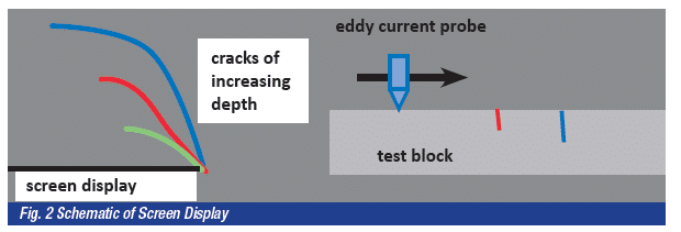
The results are displayed either as a digital read-out for the more simple examinations such as thickness measurements or displayed on an oscilloscope screen as an X-Y display of resistance versus the inductive reactance. This gives a characteristic curve, the shape and size of which can be used to detect and size a defect as illustrated in Fig.2 to determine heat treatment condition or, as a quick sorting test, to establish the type of alloy.
In addition to selecting the optimum frequency the size of the probe can be varied – a large diameter coil will inspect a larger volume of flaws. The large diameter probes are often used for the detection of large sub-surface flaws in castings and forgings and for the detection of corrosion; the small diameter pencil type probes for detecting cracks. Weld examination requires special probes to reduce noise from the permeability change across a weld.
As mentioned earlier eddy current testing can be used for a variety of inspection tasks. Chief amongst these is the inspection of welded joints using pencil probes as a replacement for the more conventional magnetic particle or liquid penetrant inspection techniques. A major advantage is that the process may be used underwater and can be used to scan welds through paint and other coatings. With respect to detection of linear defects such as cracks and lacks of fusion the defect should break the lines of the eddy currents ideally at right angles – as with magnetic particle inspection defects parallel to the eddy currents are likely to remain undetected. It is important therefore that the weld is scanned in the correct direction. Cracks as small as 0.5mm deep and 5mm in length are capable of being detected.
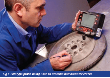
By measuring the conductivity of a metal it is possible to identify and sort both ferrous and non-ferrous metal and with certain alloys – in particular the aluminium alloys – it is also possible to establish the heat treatment condition. Low frequency probes are used to detect generalised corrosion, particularly in the aerospace industry for the examination of aircraft skins. Specially designed “bobbin” probes can be used to inspect the bore of tubes in service for signs of pitting or corrosion and there are also probes specially designed to examine the bores of bolt holes for cracks.
Measuring the proximity of a component to the probe can also be used to determine coating thickness provided the coating is non-conductive. The “lift-off”, the distance of the probe tip from the conductive surface, causes a change in eddy current flow which is measurable. All of the systems must be calibrated using appropriate reference standards – as for any NDT method, this is an essential part of any eddy current examination procedure. The calibration blocks must be of
the same material, heat treatment condition, shape and size of the item to be tested. For defect detection the calibration block contains artificial defects simulating defects; for corrosion detection a calibration block of different thicknesses is used.
The eddy current method requires more skill on the part of the operator than, say, MPI and penetrant inspection – it goes without saying that operator training is essential.