Job Knowledge 124
08 August 2017
Radiography
The previous two Connect articles dealt with the defect detection techniques of MPI, LPI and eddy current testing.
These methods are capable of detecting surface or very near surface imperfections and some process is therefore required to enable buried imperfections to be reliably detected – a so-called volumetric detection method. The first such method to be used in manufacturing to determine the quality of fabricated components is radiography. X-rays generated from a cathode ray tube were discovered in the late 1890s, soon followed by the discovery of gamma radiation fr om radioactive isotopes.
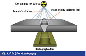
The ability of this radiation to penetrate both living and inert objects with the amount of transmitted radiation depending on the density, thickness, and atomic number of the object was eventually understood. The transmitted radiation was found to produce images on photographic film and these findings resulted in the development of industrial radiography as illustrated in Fig 1.
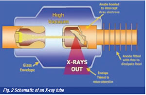
X-radiation is produced from a vacuum tube – this contains a cathode which produces a beam of electrons when an electric current is passed, the higher the voltage the more intense is the stream of electrons and the deeper the penetration – see Table 1. Industrial X-ray tubes use voltages between 20kV and some 450kV but up to 30MV in linear accelerator and betatron equipment.
The stream of electrons impacts an anode, some 1% of the energy being emitted as a beam of X-rays, the remainder being released as heat, requiring the anode to be cooled, often with water or oil. A schematic of an X-ray tube is shown as Fig. 2. The anode can be designed to provide a beam as illustrated in Fig. 2 or a 360O panoramic beam, typically used for pipe butt weld inspection with the X-ray source inside the pipe.
Gamma radiation is naturally occurring and is produced by the decay of a radioactive isotope which, when it decays, emits three types of radiation, alpha, beta and gamma. Alpha and beta radiation are short range and very easily absorbed – gamma radiation, however, is very energetic, typically over 100keV, and can easily pass through a metal, the thickness that can be penetrated depending on the type and size of isotope. The isotopes are stored in shielded containers from which they can be wound to expose the isotope, as shown in Fig 3.
Each isotope has a “half-life”- a length of time by which half (50%) of the radioactive isotope has decayed into a stable element – two half-lives means the source has only 25% of its original strength, three half-lives 12.5%. As the source decays and becomes less energetic the length of the exposure time must be increased to achieve the same density of image on the radiographic film. There is thus a point at which use of the gamma ray source is discontinued and replaced with a fresh isotope. In addition, because the gamma radiation emitted by an isotope cannot be varied in quality there is a range of material thickness for which each source will give acceptable results. The commonest isotope in regular use is iridium192 with cobalt 60 being used for very thick components.
The film is a fine grained photographic film with a coating of a light sensitive emulsion on both sides which is loaded in a darkroom into a flexible cassette. The cassette contains an intensifying screen, a card mounted thin lead foil, 0.05 mm to 0.5mm thick, held in close contact with the film. This screen absorbs stray radiation and emits electrons that enable the exposure time to be substantially reduced without affecting the radiographic quality.
The quality of a radiograph is assessed using three factors – density, contrast and definition or sharpness of the image. Most specifications require film densities in the range 1.8 to 2.5 (film density = 1, 1/10th of light is transmitted: film density = 2, 1/100th of light is transmitted). The density of the film can be measured using a densitometer; films outside of the specified range of density would be rejected. The density is affected by the exposure time and metal thickness – this can make the radiography of components with dissimilar thicknesses problematic – thin sections being over-exposed, thick sections under-exposed.
The contrast is determined by the differences in absorption between the metal and the defect and by the type of film used. The speed of the film in particular affects the contrast of the image. Most weld defects are less absorbing than the
surrounding metal – slag, porosity, lack of fusion or penetration etc therefore appear dark against a lighter background. The only weld defects that are more absorbing than the parent metal are tungsten inclusions that appear as bright white specks on the film.
Sharpness of the image is a function of a number of factors, a radiograph with poor sharpness being somewhat similar to an out-of-focus photograph with fine details being blurred or not visible. Film with a very fine grain size is preferred for high quality radiography, being capable of resolving fine details. There is a geometric unsharpness caused by the size of the radiation source, known as the “focal spot”.
A large diameter source will cause a penumbra which means that the edges of an image become blurred as shown in Fig. 4. The further away from the item being radiographed than the less obvious is this effect – unfortunately the further away the source is from the object then the longer is the exposure time – twice the distance quadruples the time. To minimise the penumbra and increase sharpness the source should be the smallest diameter possible; the film should be as close to the back of the object as possible; the source should be as far from the object as possible, bearing in mind the lengthening of exposure time; fine grained film should be used. Additional unsharpness is caused by the release of electrons within the film emulsion that darken the adjacent area.

To ensure that radiographs are of an acceptable quality with respect to image sharpness, contrast etc it is a requirement that an image quality indicator (IQI) is used as can be seen in Fig. 1.
This topic will be covered in the next Fusion, as will the techniques for radiography of a variety of joint types and component configurations.